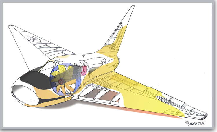
I’m really enjoying this model build, but it’s taking quite a while to progress with it. It’s quite an involved build, particularly the fuselage. I think that I may have chosen the most complicated and time-consuming way to build it!
Like I mentioned in the previous post, I used the planked method, followed by steamed and bent sections of 1/16″ soft balsa sheet glued on. I definitely should have gone down the fibreglass route…ah well.
Still, it’s looking good. both half-shells are built, sanded internally, tissue covered, doped and painted. The motor mount, motor and fan ring are glued in and the shells are now ready to be glued together. These pictures are progress ones prior to my writing this post; the model is a little further on now. The picture below shows one completed shell and the other with the moulded sheet being glued and pinned down.

Here are the completed half-shells. Notice the former crutch inside the above shell. A lot of work here!

below pic shows the 2 plywood stiffening spines that are glued inside and outside of the bottom shell. They are made from 1/16″ ply, but really I should have used 1/32″ to save weight.

Whats all those bits of junk lined up inside the lower shell? Well, I needed to weight down the inside ply strip whilst it was drying, so I used whatever bits and pieces lying around that looked heavy!

Here’s a pic of the outer ply spine glued and taped down till dry.

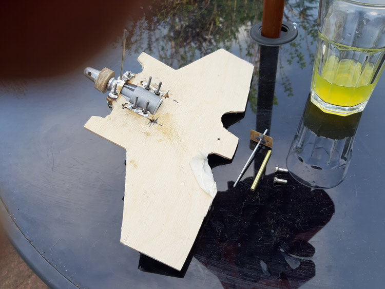
Here’s the 1/8th plywood engine plate with the glow motor mounted on. I needed to make a really sound mount system that would allow me to screw the engine bolts in without having to hold the nuts underneath. So I fashioned brass plates with nuts soldered on. The brass plates are then notched into and glued to the underside of the mounting plate. This way I can screw the bolts down without having to separately hold the nuts. Standard stuff but genius!


In the pic below are the front and rear motor mount steady rods. The rear one is on the glass table while, more difficult to see, is the front motor steady bolted to the drive shaft end of the engine.

Ok, in this pic, I’m getting the lower shell rear for cutouts for the motor mount platform. Also, you can see the dummy fan ring disc mounted to the engine. Our furry inspector is making sure I’m on top of my game..

Moving along quite nicely. The platform is notched in and glued down (Gorilla glue), fan ring made from 1/32″ ply and glued down, extra lips added to the top edge of the shell to facilitate glueing the top shell on and extra 1/16″ soft balsa doublers glued into the shell forward of the fan ring. Shaping up nicely:)

This block of soft balsa is for the cone at the back of the engine. It will have thin ply flow straighteners glued into it and then the whole assembly will be glued to the back of the platform.

There ya go! Cone set in place for fit. Still to be added in this shot are the flow straighteners. A small purposed made fuel tank will be slotted into the front of the cone, directly behind the engine and plumbed in with fuel tubing. Looking good! On with part 4.

