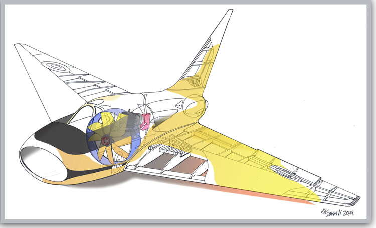
It’s March 2020 and It is now a very strange and worrying time. As I write this, The coronavirus is wreaking Havock across the planet. I hope you keep well. This post and the subsequent ones that will follow, while uploaded now were written in 2019. I hope it offers some pleasant distraction in this worrying time.

Welcome to the next installment of project Boulton Paul free flight ducted fan build! Next to building the fan, I figured that the fuselage would definitely be the most time consuming and difficult part of the build, so I held my breath and dived head-first into the build:)
In my introduction to my project I mentioned that I was going to attempt to build the body of the plane using fiberglass over a foam mould. Well in the end instead, I found myself in the model shop buying loads of sheets of balsa wood… and before I knew it, found myself creating a standard former and crutch assembly with planking over. So much for making it out of fiberglass!
Still, on with it I went. Now the formers are medium grade 1/8th balsa sheet pinned and glued down onto a central spruce strip which is screwed to the building board and over the the plan shape of the fuselage. This is taped tight to the building board. It is absolutely ridged and stable.
They are then fixed together with 1/2″x 1/16th balsa strip, pinned on top. Next individual strips of 1/16th balsa are cut and glued either side of the first strip. I did this until I had built one complete half shell. I then did the same for the other shell. I can tell you, it took AGES for me to finish the planking!

Even when i did, i thought the construction might be a bit flimsy so i decided to wrap the already planked fuse with 1/16th soft balsa sheet. The end result though once sanded, is very satisfactory and I’m pretty pleased with how the shells turned out.


The next thing to tackle was the engine and wing mount platform. This was cut from good quality 1/8th thick plywood. I decided in the end to use the ASP glow engine for power, so i made a cut-out in the platform for the engine.


Mounting holes were then drilled and eventually I got round to making the captive nuts to secure the engine. These comprise mounting nuts soldered to thin brass sheet tabs. the tabs are then anchored to underside the platform as shown in the photograph.

Now these things for an accomplished balsa beater should have been simple to put together but they were an absolute B*%^+ to make! But it doesn’t stop there! In order to create a really ridged and bomb proof mounting for the engine, The rear and the front of the platform have bicycle spoke mounting rods and they work like this:
The front spoke is soldered to a bottom brass plate cradle which is finger bent (very thin brass sheet) to suit the bottom of the engine. two holes area drilled in the plate. another brass plate is similarly bent to fit the top part of the engine and again holes drilled. The front of the engine is then clamped between the two cradles and bolted tight.

The spoke which has been soldered to the bottom cradle is then passed through the bottom of the fuselage and a spoke nipple , or similar size nut is then screwed tight up the underside of the fuselage, making a very ridged front mount. The rear mount is fashioned in the same way except instead on a cradle, a flat brass sheet is soldered to the spoke. This brass sheet is then fixed to the rear of the engine platform. Again the spoke is fed through the base of the fuse and bolted tight. BOOM! the result is a very stiff motor mount assembly, ideal for the eventual cord starting of the motor. It’s an exact copy of the mounting system used in P.E.Norman’s Javahawk and I have found it to be very effective.
